A Clutch of Differentials
Written by Alan Wenbourne in April 2007
Download this article in PDF format.
A clutch of differentials
During the construction of my 1:6 scale Meccano Hummer (previously known as HUMVEE, an acronym for the US army’s High Mobility Multipurpose Wheeled Vehicle), I learned that the Hummer is equipped with Zexel Torsen torque biasing differentials.
Further research revealed that the Zexel1 differential is that previously manufactured by Gleason, when it was known as the Gleason Torsen differential, invented by Gleasman in 1958, US patent 2,859,641.
The Torsen Differential
The Torsen (from TORque SENsing) differential, shown in figure 1, makes use of the high resistance characteristic of worm gears to being driven backwards (wheel driving worm), sometimes erroneously referred to as non-reversing. Vibration can cause a wormwheel to creep under reverse load conditions and if the lead angle of the worm exceeds the angle of friction, the wheel can theoretically drive the worm.
The Torsen differential utilizes relatively large worm gears meshing with smaller worm wheels, having a special tooth form known as Invex®. The worms are mounted on the drive (half) shafts and the wheels form planets around the worm. The lead, or helix angle, is pitched so as to allow efficient transmission from worm to wheel (when the differential cage overruns the driveshaft of the higher traction wheel), but inefficient transmission from wheel to worm (when the driveshaft of the opposite lower traction wheel overruns the cage). Thus, transmitted torque that would otherwise be reduced by the slipping wheel is biased to the non-slipping wheel.
The actual proportion of drive torque biased to the wheel maintaining traction is a function of friction (static and dynamic), velocity, load and lead angle, which are optimized at the design stage.
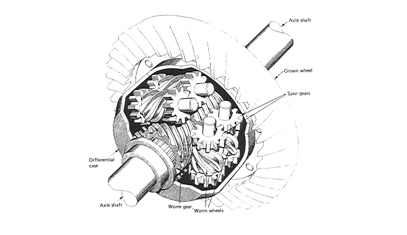
Figure 1 Three path Torsen differential
The maximum torque ratio of a particular differential design is termed ‘bias ratio’. This is expressed as the quotient of the torque in the higher torque axle divided by the torque in the lower torque axle in proportion to unity.
The choice of bias ratio provides a means of controlling the torque transfer between drive axles to achieve optimum traction. A 4:1 bias ratio design means that the Torsen differential is capable of delivering four times the amount of torque to the to the higher traction wheel, than is supported by the lower traction wheel. In comparison to a conventional or open differential, this means that under the same conditions, a 4:1 bias ratio differential is capable of delivering approximately two and one-half times more torque to the drive axles collectively than an open differential.
A comparison of 6:1 and 3:1 bias ratio and open differential performance is illustrated in the chart below.
Perfomance curve — Torsen differential
The Torsen differential is available in various capacities dependant upon the requirements of the particular application. This is achieved by changing the geometry of the Invex® gearing, providing two or three planetary gear paths, and by varying the frictional characteristics of the thrust washers or bearings supporting the worm and wheel axial loads.
There are many applications using the Torsen differential, some more notable being:
- Audi Quattro
- Hummer front and rear
- Volkswagen
- Pontiac Firebird/Trans Am
- Lexus – luxury saloon
- BMW – luxury saloon
In the past I considered the Torsen differential too challenging to model in Meccano owing to the difficulty of meshing two 14-tooth helical pinions (211a) together, or using the Meccano worm gear impractical, because of its close pitch.
However, for the sake of realistic modelling, the challenge had to be addressed! And it was, by the two path Meccano representation shown in figure 2. Unfortunately, this was too large for my Hummer model, and so started a whole new adventure.
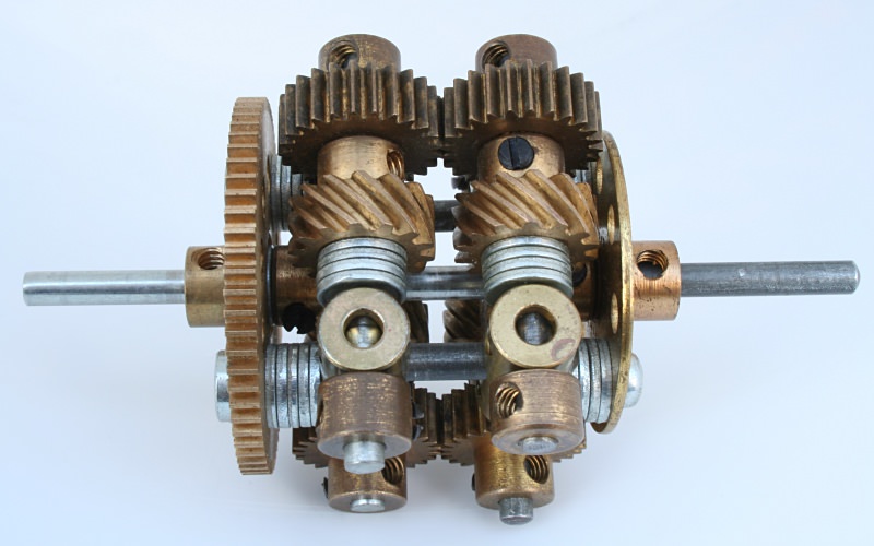
Figure 2.1 Two path Torsen type differential
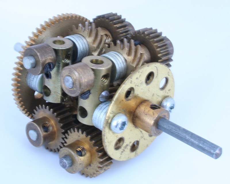
Figure 2.2 Two path Torsen type differential
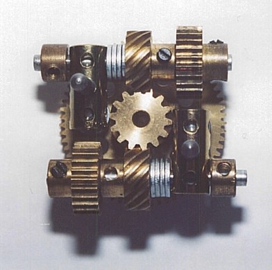
Figure 2.3 Two path Torsen type differential
Using crossed helical gears is legitimate since these are effectively non-enveloping multi-start worm gears. The main difference is that crossed helical meshing surfaces are not conjugate as with parallel axis and enveloped worm gearing, but make theoretically point contact, which increases tooth load, wear and friction.
Using helical gears in the Meccano model means that setting-up the backlash and maintaining adjacent axes at right angles is critical for smooth running. For instance, I had to check numerous new and old couplings (63) to find samples drilled accurately enough to provide control of shaft parallelism and angularity.
Even then the gear mesh was very ‘sticky’ due to the screw/wedging effect and the high degree of sliding action of crossed helicals. After many hours of adjustment and substitution of parts, followed by a duration of well lubricated running-in at high speed with a purpose made motorized test rig, I was rewarded with a smooth running assembly.
The sectional view in figure 2.3 should provide sufficient constructional detail of the unit using 14-tooth helical pinions (211a) as side and planet gears and 25-tooth spur pinions (25) as the transfer gears.
A right angle drive bevel or contrate crown wheel could be added if required and space allowed. I have modelled it as an inter-axle or third differential for compactness.
Meccano Worm Differential
The next idea was to combine the planetary worm wheels and transfer spur gears (of the Torsen design) into one pinion and mesh these with worm side gears and one another. This is made possible in Meccano because the system’s worm wheel can be a straight spur pinion, although it is not likely to work due to the close pitch of the worm (and virtual non-reversibility). The result is the arrangement shown in figure 3.
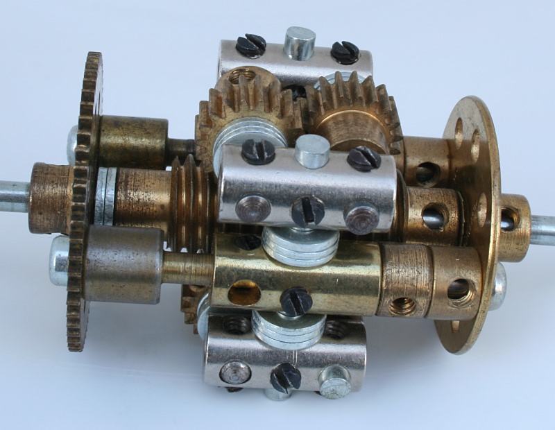
Figure 3.1 An experimental Meccano worm geared torque biasing differential
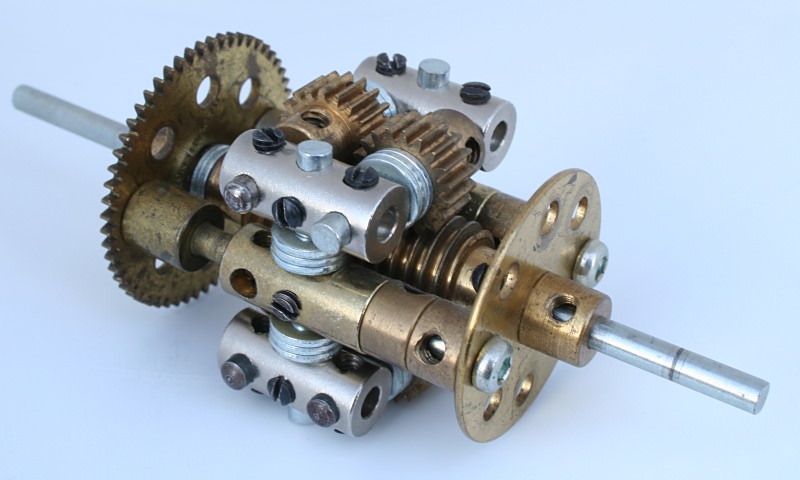
Figure 3.2 An experimental Meccano worm geared torque biasing differential
In fact this does work for small differential speeds, but locks solid when one wheel looses traction, putting full torque to the opposite wheel. It acts like screw jack (or nut and bolt), requiring a high torque to unlock it, which in reality would induce skidding and tyre scrub.
Incidentally, why is the Meccano worm gear so long? Since it is a non-enveloping single point contact mesh, it only needs to be two or thee pitches long, say ¼”, which would save space when meshing with pinions. (I note that short worms are now available!)
A New Differential Design?
After studying the Torsen unit and making the models in figures 2 and 3, I developed an alternative design and constructed two versions of it in Meccano, one using 14-tooth (211) and the other using Exacto 12-tooth (211s) helical pinions.
It occurred to me that this design might be an original idea and even a patentable invention, a possibility that I am investigating. Unfortunately, this means that I am unable to declare details of it publicly until patent protection or prior art is established. In either event, details of it could form a future up-date to this article.
Exacto Gears — Some Advice
Development of differentials using 12-tooth pinions was hampered originally through using the Exacto right hand version (211). These pinions are nickel plated, but are cut to the same dimensions as the brass finish left hand (211s) versions. Therefore, the nickel-plated parts are larger by the plating thickness of 25 microns, resulting in 50 microns less backlash per mesh. They are effectively oversize for the purpose of meshing a train of three gears on controlled centres, as required by these differential constructions.
I devoted a great deal of time to gear and involute calculations, supported by measurements of the Exacto left-handed and right-handed 12-tooth pinions, in proving them to be oversize by normal Meccano gear size, tolerance and running clearance standards. This information was forwarded to Exacto. Thus, only left-handed 12-tooth Exacto helical pinions are used in my models using crossed helicals.
Knight-Mechadyne Differential
Another design of a geared traction control differential is the Knight Mechadyne (UK patent 8,400,245, filed in January 1985, US patent 4,667,535, filed in May 1987) shown in figure 4.
The patent claims certain advantages over the Torsen type such as compactness, ease of manufacture, reduced noise in operation and better division of power. It uses continuous helicoidal section, multi-start, planetary gears.
This unit was prototype manufactured and successfully tested in a McLaren F3 race car.
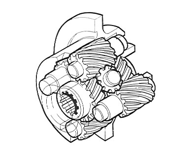
Figure 4 Knight-Mechadyne differential
Giovanni/Ferrari Limited Slip Differential
A patent search for prior art to my new design revealed some additional ideas/inventions for Meccano evaluation. One of these is the subject of US patent 4,916,978, filed in 1990, invented by Giovanni and assigned to Ferrari. This claims greater strength and durability over the Torsen design, partly through the use of more drive paths. The wheel arrangement is shown in figure 5.
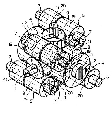
Figure 5 Wheel layout of Ferrari limited slip differential
Some experimenting with meshing Meccano gears in adjacent diagonal holes resulted in the model of the Ferrari differential shown in figure 6.
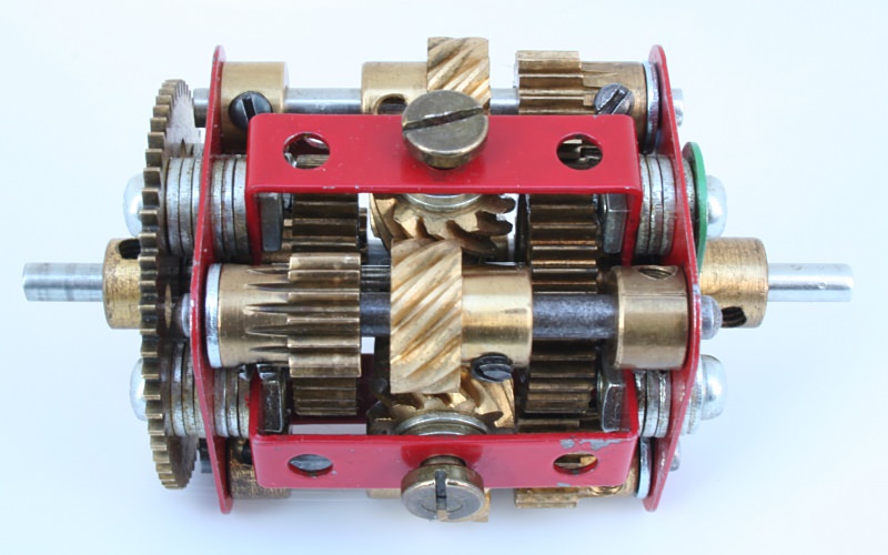
Figure 6.1 Meccano model of a Ferrari type limited slip differential
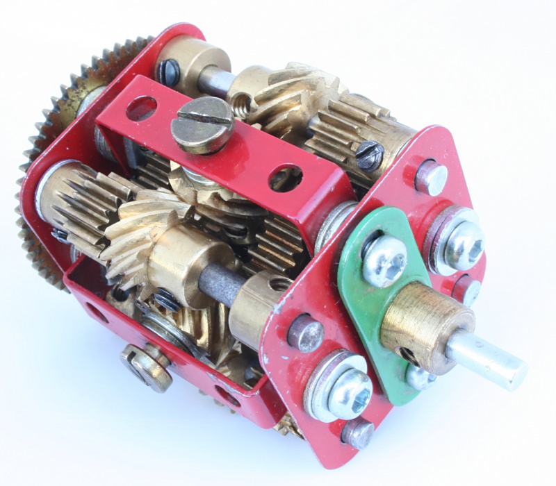
Figure 6.2 Meccano model of a Ferrari type limited slip differential
The model features four satellite 12-tooth left-handed helical gears (211) rotating about radial axes mounted on a cruciform member, a 4-hole collar (140y). These satellite gears transfer the drive to planetary helical gears (211) on a common shaft with 15-tooth planetary pinions (26c), which drive the 31-tooth (38) side gears, creating eight helical/worm meshes via four drive paths from wheel to wheel.
The theoretical load sharing contributes to the prototypes claimed high capacity and the multiple meshes increase the efficiency losses resisting wheel spin. In practice these claims are only realized through precision mounting and component manufacture, and careful running in to achieve balanced contact and load conditions.
Whilst no smaller than any of the previous models, it is an interesting alternative.
There are distinct similarities between the Ferrari and Knight Mechadyne configurations, the main differences being the single/two piece planetary gears and the use of four/two radial satellite pinions respectively.
Therefore, I regard the model in figure 6 as representative of both Knight-Mechadyne and Ferrari differentials.
Back to Torsen
The challenge of producing a more representative, triple planetary, model of the Torsen differential still existed which demanded further contemplation. Whilst toying with 12-tooth (211s) helical pinions as planets and 22-tooth (26f) spur pinions as transfer gears, it became evident that space constraints precluded the use of couplings as shaft supports. However, using strip holes as shaft journals appeared to offer a solution, provided narrow strips were used.
The differential in figure 7 uses five hole narrow strips, double bent to 29mm between bends for the planet pinion journals and 34.5mm between bends for the cage elements. Exacto small collars (59a) with grub screws (69c) retain the planet shafts.
Bolts through the intermediate holes of the 6-hole bush wheel and wheel disc carry washers and nuts on the inside, which overlap the double bent strips supporting the planet shafts for added security. The nuts have to be orientated to clear the pinions (26f).
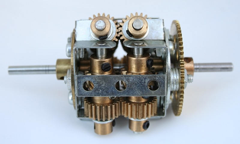
Figure 7.1 Meccano model of a Torsen type, 3 path differential
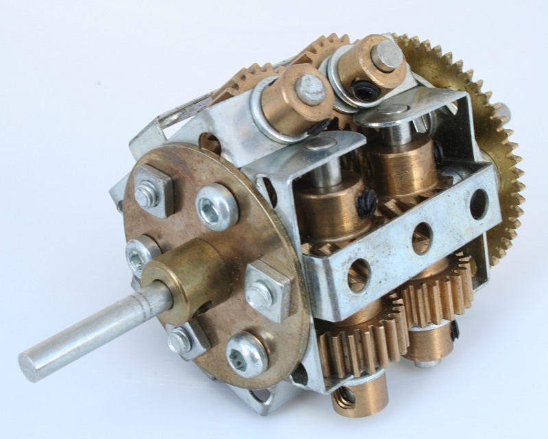
Figure 7.2 Meccano model of a Torsen type, 3 path differential
Torque Proportioning Differentials
An interesting potential variation of the Ferrari differential is that if the output side gears and planetary gears of one side were sized differently to the other side, then we have a torque proportioning, torque biasing differential — not claimed in the patent!
However, this idea is the subject of Russell/Knight-Mechadyne UK patent 8519286, filed in July 1985 (US 4,821,603, filed in 1989), as applied to the original Knight/Mechadyne principle.
A Meccano representation of this invention could be a version of the Ferrari differential with different sized side gears and planetary drivers, with just two satellite pinions. This would be both torque proportioning and torque biasing.
Torque proportioning differentials can be constructed using only spur gears, a typical arrangement being as shown in figure 8. This utilizes 6-hole bush wheels (24b) as the differential cage ends. The half shaft side gears are 13-tooth (26r) and 25-tooth (25) pinions, meshing with 25-tooth and 13-tooth planetary pinions respectively. The transfer planetary gears are 19-tooth (26) pinions.
Figure 9 shows a more compact version of the same gear arrangement.
Figure 8 Torque proportioning type differential
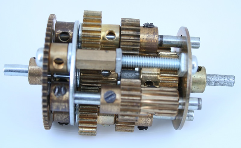
Figure 9.1 A shorter Meccano torque proportioning type differential
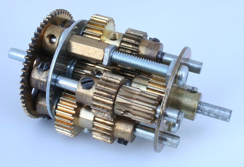
Figure 9.2 A shorter Meccano torque proportioning type differential
Further scope for variants of torque proportioning differentials was explored by considering gears meshing across adjacent diagonal holes, similar to the arrangements in figures 8 and 9. One design is that shown in figure 10, where 19-tooth pinions drive one half shaft and any combination of gears meshing at adjacent diagonal hole centres, drives the other half shaft, in this case 22-tooth planet pinions (26f) driving 30-tooth side gears (26k). The choice of combinations may only be limited by the cage design.
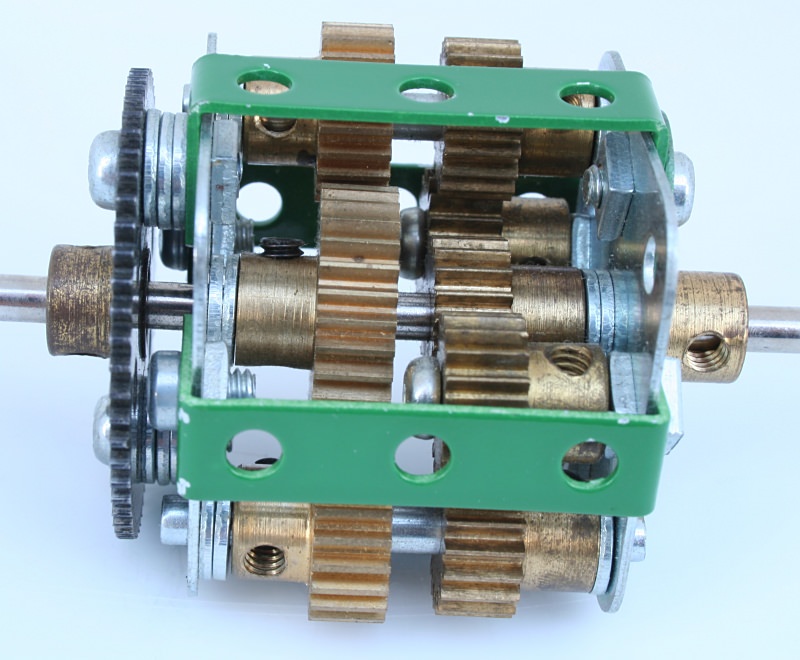
Figure 10.1 A square section Meccano torque proportioning differential
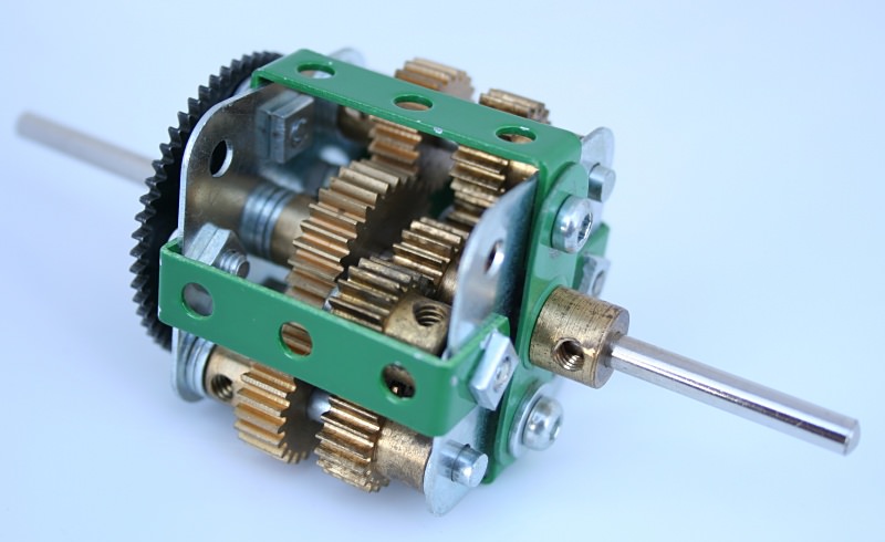
Figure 10.2 A square section Meccano torque proportioning differential
Mating side to planet gears do not have to be the inverse on the opposite side — ratios can be ‘mixed and matched’ to create various combinations. This realises eight combinations using gears meshing at one hole centre and six combinations using adjacent diagonal holes as shown in the table below, creating an impressive range and choice of torque proportioning combinations.
Torque Proportioning Combinations
| Ctrs (ins) |
|
No. of teeth in side/planet gear |
Torque Proportion |
| |
|
LH Gear |
LH Planet |
RH Gear |
RH Planet |
LH % |
RH % |
| 0.5 |
|
13 |
25 |
25 |
13 |
34.2 |
65.8 |
| |
13 |
25 |
22 |
15 |
37.1 |
62.9 |
| |
15 |
22 |
22 |
15 |
40.5 |
59.5 |
| |
13 |
25 |
19 |
19 |
40.6 |
59.4 |
| |
15 |
22 |
19 |
19 |
44.1 |
55.9 |
| |
13 |
25 |
15 |
22 |
46.1 |
53.6 |
| |
22 |
15 |
19 |
19 |
53.7 |
46.3 |
| |
25 |
13 |
19 |
19 |
56.8 |
43.2 |
|
| 0.707 |
|
19 |
19 |
38 |
15 |
33.3 |
66.7 |
| * |
22 |
30 |
38 |
15 |
36.7 |
63.3 |
| |
19 |
19 |
30 |
22 |
38.8 |
61.2 |
| * |
22 |
30 |
30 |
22 |
42.3 |
57.7 |
| * |
30 |
22 |
38 |
15 |
44.1 |
55.9 |
| |
19 |
19 |
22 |
30 |
46.3 |
53.7 |
* These combinations would be of the ‘Ferrari’ type construction.
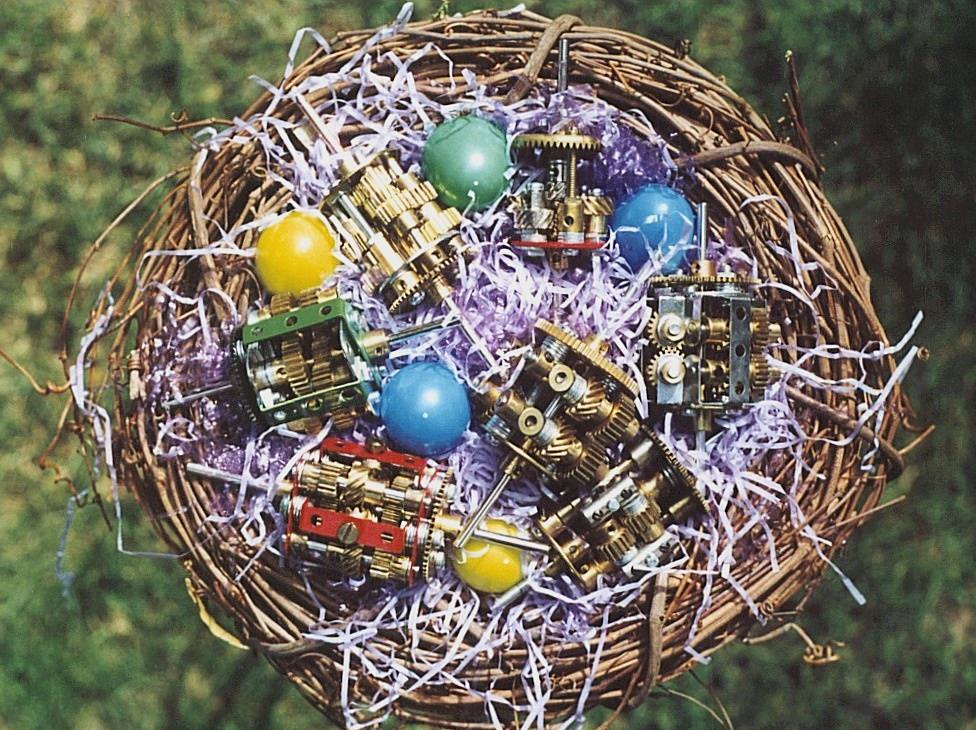
In conclusion, the ‘cuckoo in the nest’, whilst not a torque biasing or proportioning differential, takes advantage of the fact that left-hand and right-hand helical gears will mesh on adjacent parallel shafts, demonstrated here in the form of an open differential in figure 11.
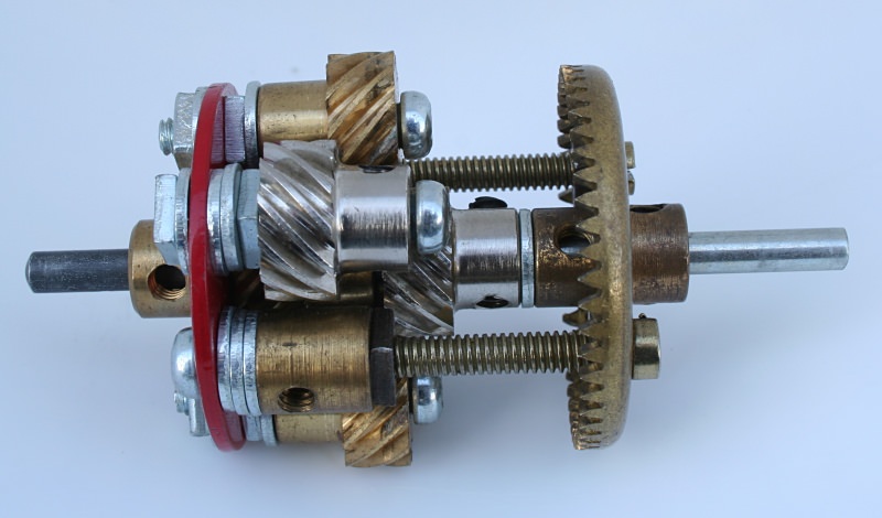
Figure 11.1 Meccano open helical geared differential
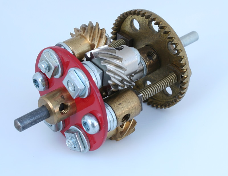
Figure 11.2 Meccano open helical geared differential
Footnotes
- Torsen® is currently owned by the JTEKT Corporation.
This article © 2007 Alan Wenbourne.