Compact Six Speed and Reverse Gearbox
Written by Alan Wenbourne in September 2012
Download this article in PDF format.
The Gearbox
During the construction of my demonstration Direct Shift Gearbox (DSG) transmission I thought that sometime I might design a more compact six speed and reverse gearbox better suited for realistic scale models.
I was aware of the late Tony Bolton’s design as published in Constructor Quarterly issue 37 (September 1997), and in reviewing his excellent model, decided that I was unlikely to better it. Tony’s compact six speed and reverse gearbox is an ingenious all-pinion design of exceedingly robust construction and economy of parts.
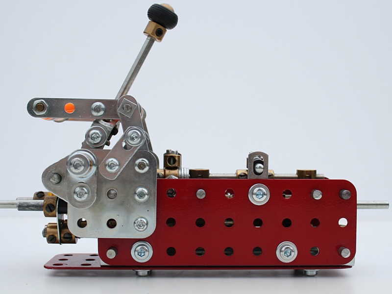
Figure 1 The six speed gearbox in elevation
In the Constructor Quarterly article Alan Partridge deals with the description and construction of Tony’s model in full detail and suggests that it may be possible to produce an even more compact version using narrow face pinions.
One of the most difficult areas of gearbox design and construction is in the gear change mechanism, which is often as challenging as the gearbox itself. I have not seen any applications of Tony’s gearbox or solutions to the shifting dilemma, so maybe I could complement Tony’s design in attempting to create a gearshift mechanism? Such a mechanism would have to be as compact as possible to do justice to Tony’s model, which I hope I have achieved in the following description.
Watch our video of this model
Stage 1
Stage 1 was to build a modification of the model incorporating narrow face pinions where applicable. This enabled an overall length saving of one inch, as illustrated in figure 2, which also identifies all the significant additional and changed parts. The relevant parts used in the original model are shown in parenthesis.
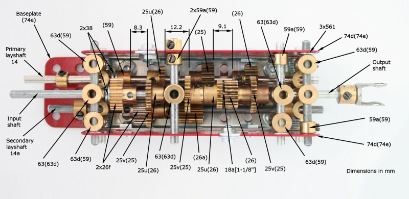
Figure 2 Identification of parts in the modified gearbox
The body of the model is № 4½” instead of 5½” long. I used a 5½” long Flat Plate for the base because I hadn’t got three 4½” plates! However, the longer base plate may prove useful for attaching or supporting a clutch housing later.
Gear spacing is shown for the primary lay shaft. The gears on the secondary lay shaft are not spaced. I measured the gear spaces using twist drills as ‘Go/No-Go’ gauges. For reference in setting-up, these were: 21/64” (8.3mm), 23/64” (9.1mm) and 15/32” (Go), and 31/64” (12.2mm) (No-go).
My description only covers the additions and significant parts changes; I assume readers will have access to the original Constructor Quarterly article for the constructional and other detail.
Stage 2
Figure 3 shows the shift rods with built-up detent grooves using washers. The rods are journalled into the additional Short Couplings. The central upper Axle Rod is for supporting the spring loaded detent fingers and is secured by the Grubscrew (69) identified.
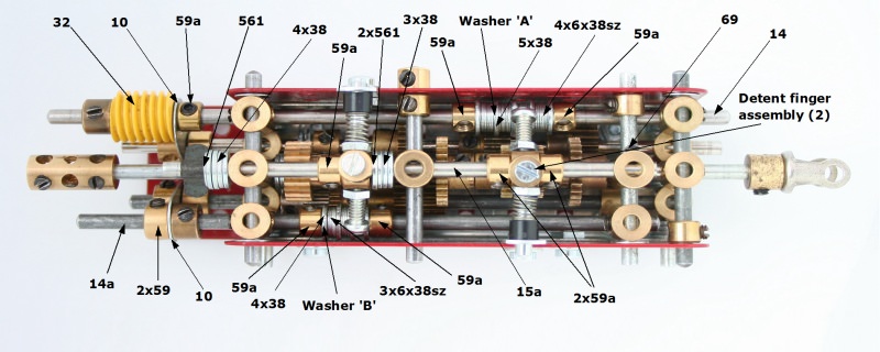
Figure 3 Addition of the shift rods and detents
For reference, the small Washers (38sz) are M4 x 7.7mm (0.303”) OD x 0.054mm (0.021”) thick. The washers marked ‘A’ and ‘B’ may need slightly reduced outside diameters to clear the adjacent 25-tooth pinions. I found 0.010” (0.25mm) reduction in diameter sufficient.
Figure 4 shows the shift rod Fishplate connections to the lay shafts. Note that the shift rods should be journalled through the Fishplate holes and gripped by the collars. The lay shafts journalled through the Fishplate slotted holes should have their Collars set for minimum running clearance.
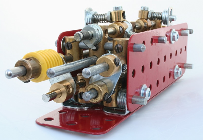
Figure 4 Detail of the selector rod to lay shaft connections
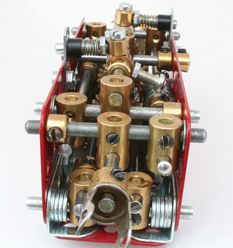
Figure 5 Output end view showing lay shaft and shift rod journals
Figure 6 is a close-up of the spring-loaded detent fingers and parts identification. Note the use of hexagon nuts for clearance purposes. Also, due to the angular spacing variations of three hole collars, they require careful selection to provide the necessary angular orientation.
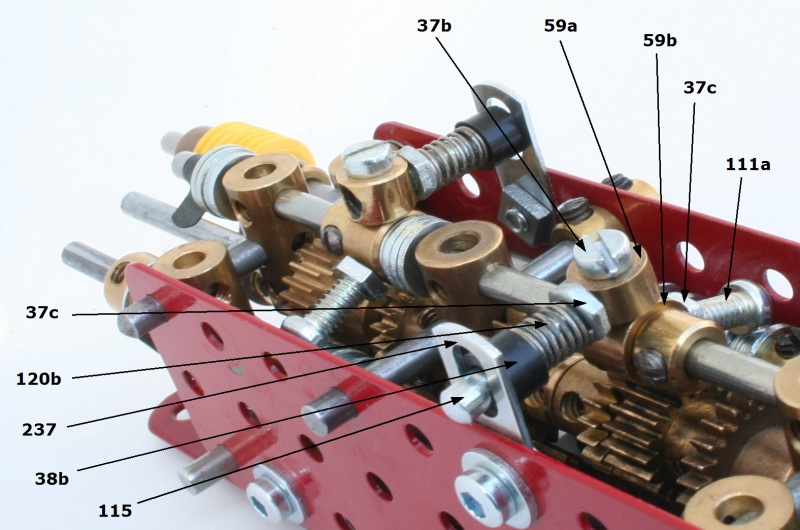
Figure 6 Detent finger detail
The three-hole collars are free to oscillate on the Axle Rod. The Aero Collars (59a) are secured to the three-hole Collars with 9/32” long cheese head Bolts (37b).
I found it useful at this stage to run the gearbox using a low power drive motor, selecting each ratio to check for proper engagement and neutral spacing between each gear. This can be exceedingly tedious and time consuming initially, but should be less so if accurate spacing is applied during setting-up.
Stage 3
Figures 7 and 8 show the addition of the selector mechanism to convert transverse lever movement into longitudinal movement of the primary selector rod/lay shaft assembly.
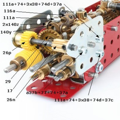
Figure 7 Primary lay shaft selector mechanism and mounting arrangement
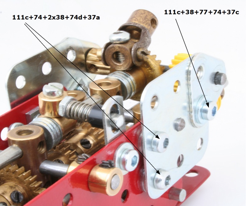
Figure 8 Primary lay shaft selector mechanism and mounting arrangement
This configuration assumes the gearbox is applied to a front powered, rear wheel drive vehicle, where the driver sits over the gearbox facing the prime mover. The lever motion then provides R-1/2–3/4–5/6 gear selection from left to right, as per figure 12.
It proved necessary to include step-up gearing in order to limit the angular movement of the gear lever, hence the compound pinion arrangement.
The Contrate (29) is free on its Axle Rod and shimmed with Washers for minimum backlash with Pinion (26n). Note that the brass (26n) was later replaced with a cast version, plastic spacers and washers to permit full stroke of the gear lever; see figures 9, 10 and 11.
Stage 4
Figures 9, 10 and 11 show the addition of the mechanism for control of the secondary lay shaft. Note that the inboard collar (59) on the secondary lay shaft (14a) shown in figure 2 is replaced with a small plastic spacer (38b) and a mini collar (59a). A 3/8” bolt (111a) carrying an additional mini collar (59a) is screwed into this. A shoulder bolt (140z) secures a 3-hole narrow strip (235g) to the second mini-collar as shown in figure 9.
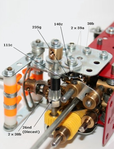
Figure 9 Secondary lay shaft connection
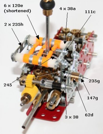
Figure 10 Secondary lay shaft shifter and gear lever gate
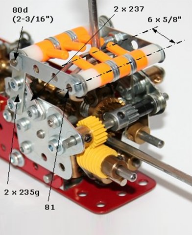
Figure 11 Gear lever gate parts detail
The slotted section of a slotted strip (245) is curved to approximately a 1¾” radius and is attached to the 3-hole strip (235g) via the pivot bolt (147g), and nut/bolt/washer as shown in figure 10. Figures 10 and 11 identify the significant parts of the gear lever gate arrangement.
The Mini Shock Absorber Pins (120e) are shortened as shown; I would have used a less garish colour if I had had more stock!
At this stage I changed the input shaft to a tri-flat axle rod to accommodate a new diaphragm clutch that I had designed to operate with this gearbox.
For reference, the gear ratios are:
| Gear |
Ratio |
| 1st |
3:1 |
| 2nd |
2.28:1 |
| 3rd |
1.73:1 |
| 4th |
1.32:1 |
| 5th |
1:1 |
| 6th |
0.76:1 |
| Reverse |
2.28:1 |
Figure 12 Gearshift gate pattern
The Clutch
Having completed the gearbox and selector mechanism, it is logical that a clutch would be required.
For some time I had wanted to replicate the typical automotive diaphragm clutch, but could not improvise or simulate a diaphragm spring in Meccano as no such spring exists in the system. However, experimenting with the newly acquired 2½” diameter Circular Strip (145a) led to the design used here. Although not a diaphragm spring, its action simulates that of the real thing.
For this application I constructed a mounting frame to support the clutch and provide means of attaching it to the gearbox. Also, for demonstration purposes at least, the clutch throw-out and release pedal are included in the same assembly.
For what would be the engine flywheel to which the clutch is assembled, I chose to use a 2½” diameter 95-tooth Gear (27c), to provide the option of driving it directly or via its teeth. The pressure plate is a 2½” Face Plate (109). A 2½” Circular Strip (145a) forming the spring reaction member is sub-assembled to the pressure plate with four Pivot Bolts (147b) carrying Narrow Fishplates (237) and Compression Springs (120b), as shown in figure 13.
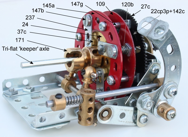
Figure 13 General view of the clutch with significant parts annotated
The withdrawal member is a Bush Wheel (24) carrying four bolts with Hexagon Nuts (37c) on the boss side of the Bush Wheel, with their curved face outwards. The friction plate is a 1” Plastic Tri-Flat Pulley (22cp3p) fitted with a Rubber Tyre (142c). These parts are assembled to the 95-tooth Gear with Pivot Bolts (147g) and nuts in the order shown. It is a good idea at this stage to insert a Tri-Flat Axle Rod into the bore of all the parts, and secure it temporarily, to maintain concentricity of the friction plate.
A Socket Coupling (171) is secured to the boss of the Bush Wheel for use as a throw-out bearing.
The clutch operates smoothly and with a nice ‘feel’ in operation. It has considerable holding power such that when overloaded, the Rubber Tyre slips rather than the Pulley, so it should have adequate capacity for most Meccano applications.
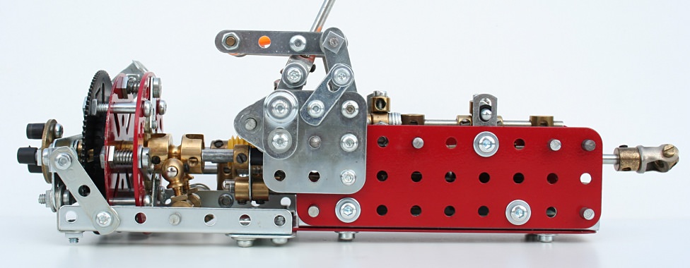
Figure 14 The complete transmission
See more photos of this model.
Additional Notes
The gearbox has three lay shafts; two sliding (‘L1’ and ‘L2’) and one fixed (‘L3’). These are indicated in figure 15, an amended version of Alan Partridge’s diagram 1 from issue 37 of Constructor Quarterly.
Figure 15 Lay shaft and gear layout
Also denoted are the gears, in lower case letters. The input shaft has pinions ‘a’ and ‘b’, lay shaft ‘L2’ has ‘j’, ‘k’ and ‘l’, lay shaft ‘L3’ has ‘c’ and ‘d’, and the output shaft has ‘e’ and ‘f’. I have retained Alan Partridge’s lay shaft positions ‘A’ to ‘F’. The lay shaft positions and drive paths for each gear are as shown in the following table:
| Gear |
Lay shaft positions |
Gears in mesh
(drive path) |
Ratio |
| |
L1 |
L2 |
|
|
| 1st |
B |
C |
a-j; l-c-g; h-e |
0.76:1 |
| 2nd |
A |
C |
b-k; l-c-g; h-e |
1:1 |
| 3rd |
B |
D |
a-j; l-c; d-h-e |
1.316:1 |
| 4th |
A |
D |
b-k; l-c; d-h-c |
1.731:1 |
| 5th |
B |
E |
a-j; l-c; d-h; i-f |
2.278:1 |
| 6th |
A |
E |
b-k; l-c; d-h; i-f |
2.997:1 |
| Reverse |
A |
F |
b-k; l-h; i-f |
2.278:1 |
These additional annotations should help in following the function and operation of the gearbox, and also apply to the gearbox featured in issue 93 of Constructor Quarterly except for the scale, gear widths and spacing.
This article © 2012 Alan Wenbourne.