Ravigneaux Planetary Transmission
Written by Alan Wenbourne in April 2006
Download this article in PDF format.
Seizure of the 5-speed crash-change gearbox in my model H1 Hummer vehicle prompted the desire to replace it with a more robust and, possibly, more authentic version.
The 5-speed unit, shown in figure 1, uses sliding gears on keyway axle rods, which was its downfall, since the magnitude of torque required to drive the model is too much for keyed rods and key bolts. The key bolts embedded themselves into the soft steel shaft and jammed solid. I did consider having some keyway axle rods hardened, but decided on a different approach.
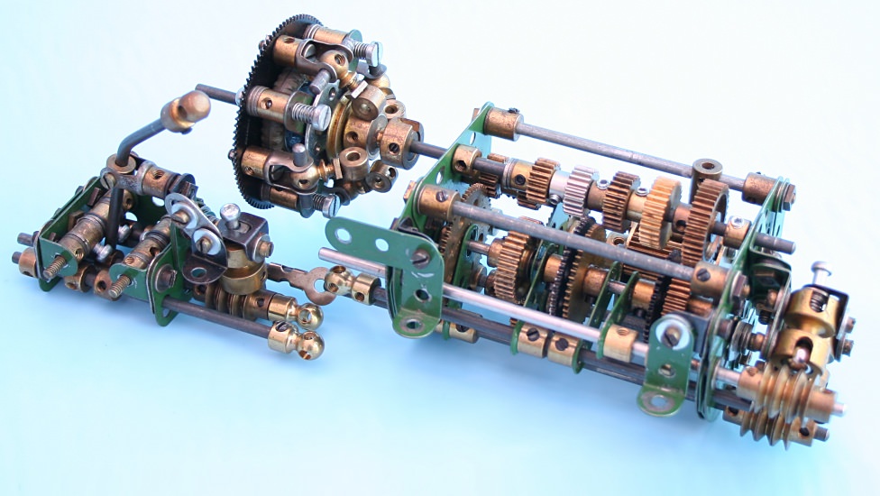
Figure 1 Hummer 5-speed gearbox, clutch and shifter
The actual Hummer uses an Allison M74 1000 series 5-speed automatic transmission with high/low transfer case. A planetary gearbox would have been the closest to modelling an automatic, but I resisted this because of the size and complexity of creating such a gearbox using 3½” ring gears.
Since the 2½” ring gear became available I began formulating some ideas for using the smaller ring gear in a Ravigneaux configuration. This would enable a 3-speed and reverse unit using only one ring gear, and the addition of a high/low range change with inter-axle differential and diff-lock, would represent the actual vehicle more realistically.
The Ravigneaux planetary gear arrangement has been used in many automotive automatic transmission systems. I based my research and analysis on the Borg Warner model 8 & 35 transmissions used in many European cars in the 1960s and 1970s, shown in figure 2.
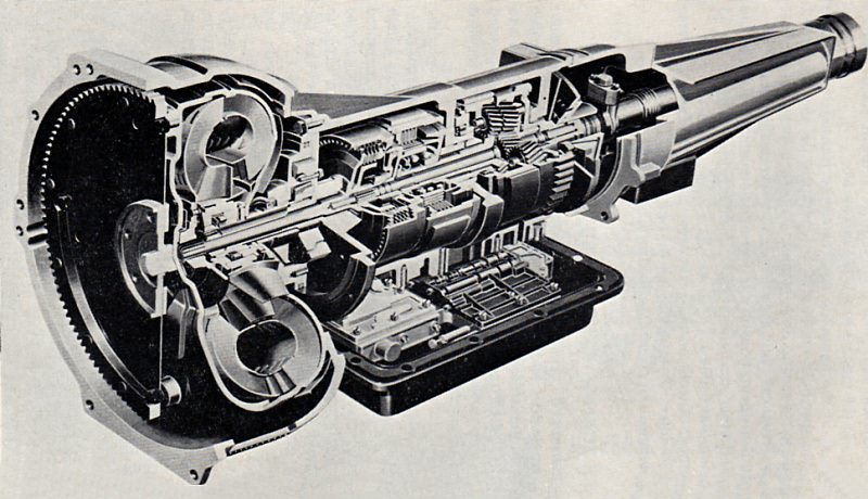
Figure 2 Cutaway section of Borg-Warner model 35 transmission
Figure 3 shows the planetary gear arrangement used in these transmissions — the figures are the numbers of teeth on the gears for model 35; those encircled are for model 8. Figure 4 is a schematic of the transmission.
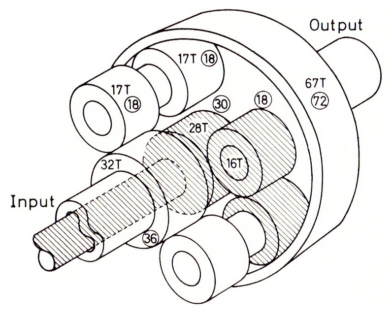
Figure 3 Ravigneaux gearset used by Borg-Warner
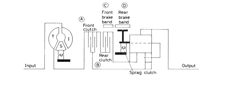
Figure 4 B-W model 8 and 35 transmission schematic
The arrangement of hydraulically actuated clutches and brakes of the actual transmission are difficult, if not impossible, to reproduce mechanically in Meccano, so an alternative scheme is required where all the clutched and braked elements are accessible externally.
Such a scheme was devised and the layout added into a spreadsheet with descriptive data and gear ratio calculation charts, as shown in figure 5.
Figure 5 Gear schematic, spreadsheet and charts
Development of the Meccano Model
The Ravigneaux gearset is defined as an epicyclic gear arrangement having two sun gears and pairs of meshing planet gears, one planet meshing with one of the sun gears, the other meshing with the annulus gear, as shown in the diagrams, figures 3, 4 and 5. The primary train being s1, p1, p2a and a, with the secondary train: s2 and p2b, p2a and p2b being fixed on the same shaft.
The obvious starting point was to consider which Meccano pinions would mesh between the adjacent radial and peripheral holes of an 8-hole bush wheel acting as one side of the planet carrier, with a 57-tooth gear for the other side.
This soon proved impractical, so a 6-hole bush wheel was considered for the carrier element.
After trying many options and checking the resultant ratios, the best combinations were 19:19 and 22:15.
In theory, the 22:15 combination is not meant to mesh together, because the 22-tooth pinion is designed to mesh with the 55-tooth wheel, an equivalent centre distance of 37 teeth. Standard Meccano gears are 38DP (Diametral Pitch), so one or both gears have to be profile shifted (non-standard) to mesh effectively at ½” spacing. Similarly, the 15-tooth pinion is designed to mesh with the 60-tooth wheel, a centre distance equivalent to 37.5 teeth. So one or both are non-standard. Despite all this, 22:15 do mesh quite well together!
This combination was used as the secondary train in a Ravigneaux model with 19-tooth pinions as the primary train, shown close-up in figure 6. This gearset was developed in a ‘breadboard’ or prototype model, shown in the general view figure 7.
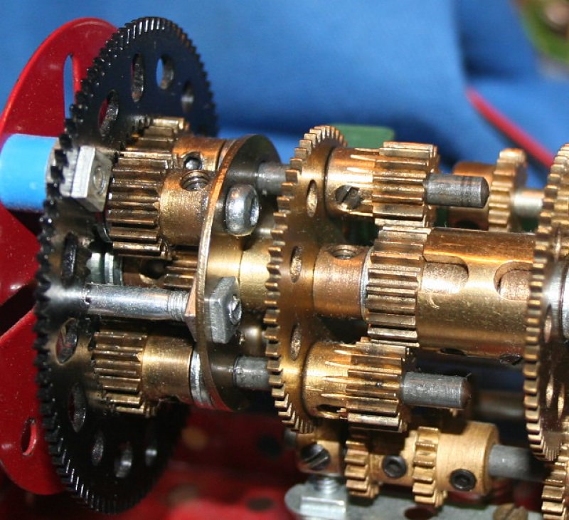
Figure 6 Prototype model Ravigneaux gearset
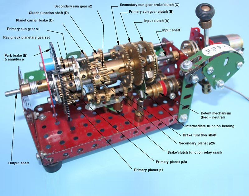
Figure 7 General view of the prototype Ravigneaux gearbox in 2nd gear, with elements identified in accordance with the notations given in figure 5
The prototype model formed the basis for developing the principle of using a sliding shaft with rotating ½” pinions attached, as the clutching elements, and a second sliding shaft with fixed narrow faced ½” pinions, for the braking functions. A relay crank connects these two shafts such that they slide in opposite directions.
The clutch elements are 57-tooth gears, with ‘B’ attached to the primary sun gear (s1) shaft and ‘C’ to the secondary sun gear (s2) by socket coupling. The sliding 19-tooth pinions are set-up so as to connect sequentially, the input with s2 (reverse gear), input with none (neutral), input with s1 (first gear), input with s1 (second gear) and input with s1 and s2 (third gear — direct drive). This sequence satisfies the clutch functions described in the block chart of figure 5.
Simultaneously, the brake relay shaft slides to engage in the holes of the 2½” ring gear (park), then the narrow face 19-tooth pinions engage with the planet carrier 57-tooth gear ‘D’ (reverse), none (neutral), planet carrier 57-tooth gear ‘D’ (first gear), 57-tooth gear ‘C’ (second gear), completing the brake functions shown in the chart of figure 5.
This sliding action produces the shift sequence: P-R-N-D1-D2-D3 as required. A 2½” faceplate carrying the 2½” ring gear forms the gearbox output. A spring loaded pivot bolt passing over a suitably spaced stack of ½” pulleys, detents the selected gear positions. The whole assembly is supported between two 2½” x 2½” flat plates attached to a 5½” x 2½” flanged plate.
After much tedious experimentation to achieve the correct sequencing, spacing between gears and backlash reduction in the sliding elements, the prototype model proved the principles of operation. However, using a bush wheel and a bushed 57-tooth gear as the planet carrier, made the assembly longer than I wanted, also, the 15-tooth planet pinions were a compromise to achieve clearance with the 19-tooth brake shaft pinions. The ratios achieved were: 3:1, 1.66:1, 1:1 and 2.05:1 reverse, not quite as good a ratio set as those achievable by using 19-tooth pinions throughout — see chart figure 5, case 2.
Figure 8 is a plan view showing the clutch function shaft in more detail. Figure 9 shows, in close-up, the brake function shaft anti-rotation coupling/control rod and the detent spring mechanism.
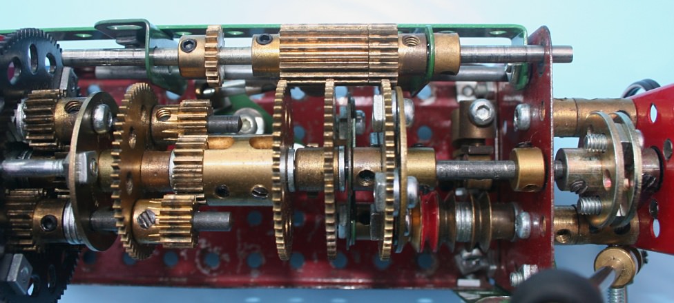
Figure 8 Showing clutch function shaft — in 3rd gear
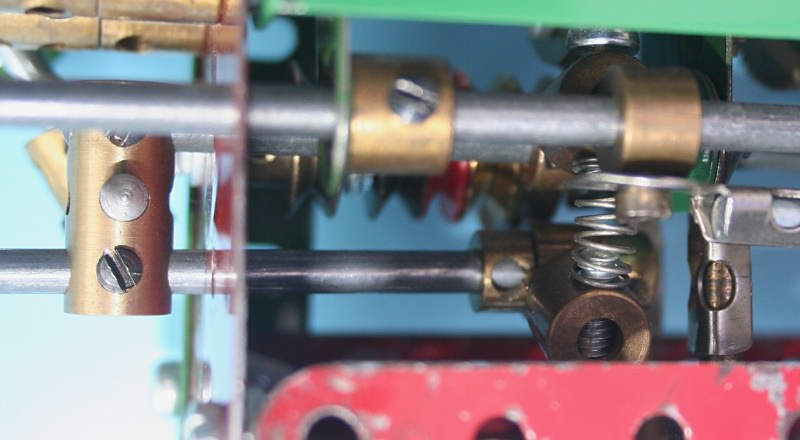
Figure 9 Showing brake shaft anti-rotation coupling on gear selector rod and detent spring
The next stage was to develop a definitive model incorporating a more compact Ravigneaux gearset, inter-axle differential, diff-lock and Hi-Lo range change. Also, it would be desirable to overcome the close clearance between the orbiting planet gears and the brake function gears.
One method of reducing the length of the planetary set would be to obtain a 6-hole 57-tooth gear and use it as one side of the planet carrier. Stuart Borrill duly obliged with the 6-hole 57-tooth gear and a new planetary set was constructed (fear of forgetting how the prototype was constructed, necessitated a completely new, additional model!).
Testing proved the necessity to add wheel discs to the 6-hole 57-tooth gear in order to provide better journals for the compound planet gear shafts. Otherwise these would skew under load and create poor meshing conditions with the mating pinions — the penalty: extra length! But this is still ¾” (19 mm) shorter than the prototype.
To overcome the clearance issue, I decided to add extra narrow facewidth 19-tooth pinions, in constant mesh with the two 57-tooth brake gears ‘C’ and ‘D’, which would position the brake function shaft further away from the planetary set. A peripheral advantage of doing this is that it facilitated the 19-tooth planetary set with its preferable ratios.
There was insufficient space to accommodate the prototype detent mechanism, so a more compact system using stacked large spring supports was devised and an axial plunger type detent pin employed, made-up from a collared, spring loaded 1” axle rod, journalled in a short coupling, as shown in figure 12.
These improvements and changes were built into a different mounting framework, which I chose to base on 2½” triangular end plates extended with square and triangular plates at each end.
This enables the shafts to be wrapped into the most compact arrangement. A central 2½” triangular plate supports the input and planetary shafts, also providing journals for the control and detent rods.
The whole is mounted onto a 2½” x 5½” flanged plate for convenience and stiffness. Additional longitudinal ties of 5½” double bent strip and narrow angle girder provide extra support and stiffness.
A high-low range gear change using narrow faced 19-tooth and 38-tooth gears and a spur gear differential with lock completed the gearbox as shown in figure 10.
Other details are shown in figures 11, 12 and 13. ‘Drivers-side view’ refers to left-hand drive application.
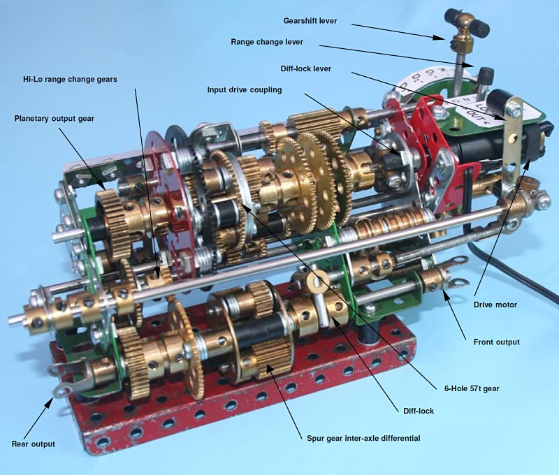
Figure 10 General view of Ravigneaux transmission in 1st gear
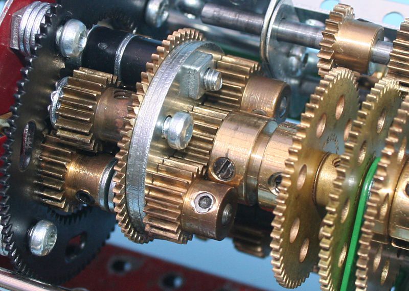
Figure 11 Close-up of ‘compact’ Ravigneaux gearset
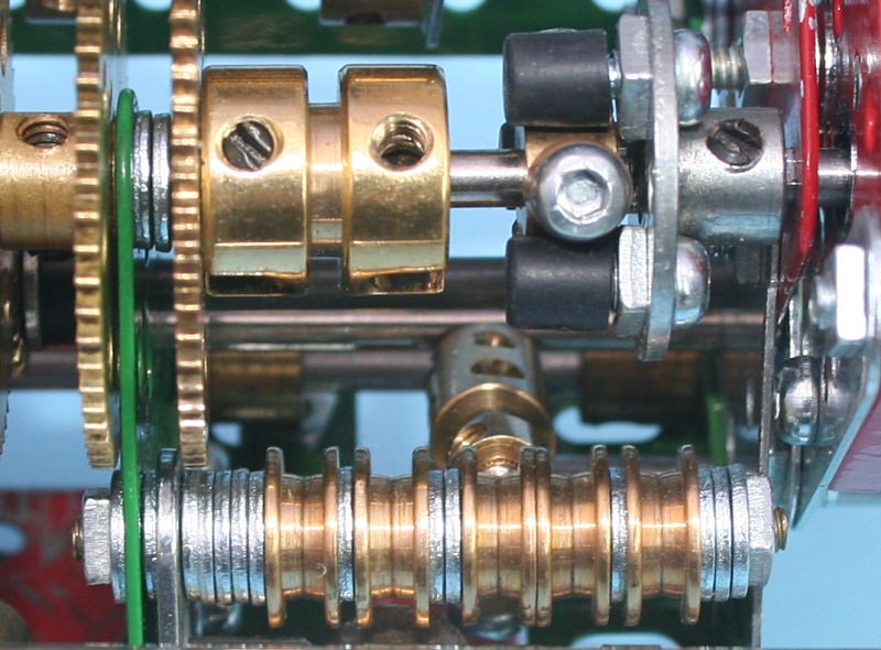
Figure 12 Detail of detent rail — 1st gear position
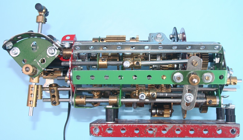
Figure 13 Drivers-side view showing clutch/brake relay crank in 1st gear
The ratio comparison of model to vehicle is given below. It’s not a bad match since I lost two speeds!
| Gear |
Meccano Model |
H1 Alpha Hummer |
| |
High Range |
Low Range |
High Range |
Low Range |
| 1st |
3:1 |
9:1 |
3.10:1 |
8.43:1 |
| 2nd |
1.5:1 |
4.4:1 |
1.81:1 |
4.92:1 |
| 3rd |
1:1 |
3:1 |
1.41:1 |
3.83:1 |
| 4th |
- |
- |
1:1 |
2.72:1 |
| 5th |
- |
- |
0.71:1 |
1.93:1 |
| Reverse |
3:1 |
9:1 |
4.49:1 |
12.21:1 |
Conclusion
Figure 14 shows the Ravigneaux transmission installed in the Hummer chassis. Despite its size, it fitted within the frame very easily, with the controls nicely positioned.
So far, it has proved sufficiently robust for this heavy model and durable in operation. Gear shifting can be executed on the move easily and with little loss of momentum. A great improvement over the 5-speed crash change box, which discouraged one from making gear changes!
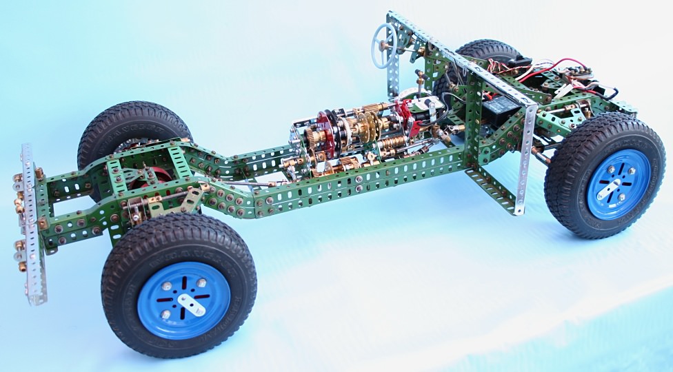
Figure 14 Ravigneaux transmission in 1:6 scale H1 Hummer chassis
This article © 2006 Alan Wenbourne.