The Heatherwick Rolling Bridge
Written by Alan Wenbourne in September 2008
Download this article in PDF format.
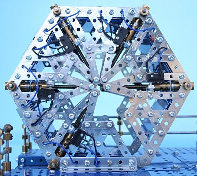
Figure 1 This is a bridge?
Introduction
In 2006 Thomas Heatherwick won the ‘British Designer of the Year’ award for his unique rolling bridge, which he created for pedestrians to cross part of the Grand Union Canal, at the new commercial development in London’s Paddington Basin, shown in figures 2 to 4.
Although the bridge has become known as a ‘rolling bridge’, a more accurate description of its action is that it curls — someone said “like a scorpions tail”.
The 12.9m long bridge spans an 8.5m canal inlet and has eight sections hinged at the walkway level. At each hinge point there are two cylindrical rams, one each side of the walkway. Each ram acts to fold the handrails so as to draw the sections together, as shown in figure 5. The completed action results in an octagonal folded structure.
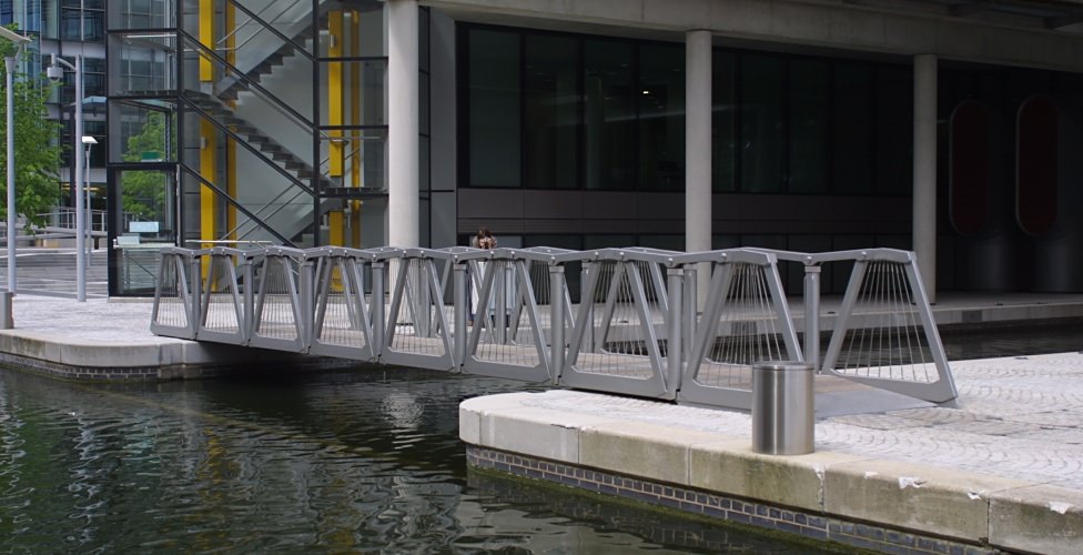
Figure 2 The Heatherwick Rolling Bridge
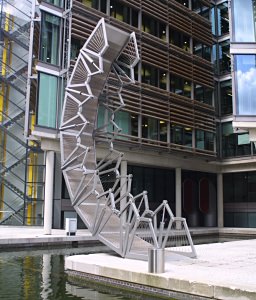
Figure 3 Rolling
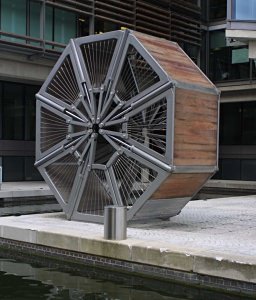
Figure 4 Rolled up
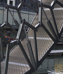
Figure 5 Cylinders
The Hydraulic System
An 11kW hydraulic pump drives a 400mm diameter master cylinder. This is mechanically linked to fourteen 160mm diameter slave cylinders, each of which independently drive the fourteen 100mm diameter bridge operating cylinders at a constant rate (constant volume) as shown in figure 6 (note the master cylinder inside the nest of slave cylinders and the flexible hoses leading to the bridge, where they are routed through the void between the decks).
The hydraulic pumps and associated equipment are mounted on a suspended platform that is located in the basement of an adjacent building, making the bridge eerily silent in operation and resulting in a delicate balance of art, machine and structure. It is designed to open in 180 seconds.
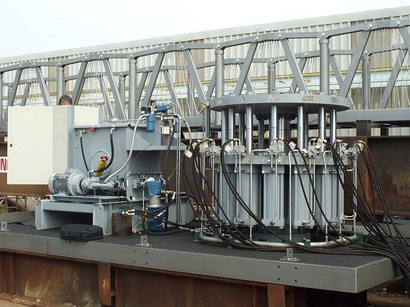
Figure 6 The hydraulic equipment, showing the master and slave cylinder drive arrangement
On reading an article about this remarkable feat of design and engineering in the Daily Telegraph, I became enthused with the idea of modelling it in Meccano, or at least using as much Meccano as possible!
The original, being hydraulically operated by the system described above ensures that each section folds at the same rate, but this technology obviously does not lend itself easily to a Meccano solution.
Meccano Model Development
It is important to note that the rolling (or curling) action is constant for each bridge section (the startled woodlouse analogy mentioned in the Telegraph article!) as opposed to the action of rolling a carpet, or one of those party whistle things.
Initially I embarked on a gear driven screw jack system for the folding mechanism. This is not nearly as elegant as the original, but should have be effective in that it would support the relatively high forces involved during the initial folding phase.
The bridge sections would need to be as light as possible because the first stage folding mechanism has to raise all but one of the sections, rather like raising a crane jib from the lower pivot point!
I decided to make the bridge sections from standard strips at the floor level with narrow strips forming the sides. In making the first two sections I got the angles wrong, as it would fold into a hexagon, not an octagon like the original. This appeared to have advantages in that such a design would be lighter and have only five mechanical stages as opposed to seven for the octagonal configuration — so I decided to proceed on the basis of a six section hexagonal design at approximately 1:20 scale.
Watch Heatherwick Studio’s video of this model
A Geared Solution
If a geared system could be made to work it should ensure the equal angular displacement of each section as required. So a long period of development ensued experimenting with mechanical drive arrangements capable of withstanding the load variations and frictional resistance.
A fairly compact screw jack, seen in figures 7 and 12, driven with 16-tooth Bevel Gears (part 30h), proved to be a better (but more expensive) solution than using 25-tooth Contrate Gears (part 29) and minimized the intrusion of the screw jack mechanism into the footpath. The teeth of these bevel gears were truncated at their outside diameter to accommodate them within the legs of the Narrow Double Brackets (part 811a).
Initially, the bevel gears driving the jacks were secured to the axle rod forming the bridge section hinge, with a 25-tooth Contrate Gear (part 29) at its centre, driven by a 19-tooth Pinion (26) on an Axle Rod, running parallel with the longitudinal centre line of the bridge, under the floor. This arrangement was repeated to transfer the drive from one section to the next.
The first problem this presented was that for two screw jacks on the same shaft (one each side), one jack extended whilst the other retracted. Turning one jack round to reverse its action meant that it protruded further into the footpath (figure 7) – this I considered unacceptable. Another (unavailable) solution would be left hand threaded components.
I then proceeded with jacking one side only, alternating the jacking side from section to section, and by transferring the drive from each section to the next, by alternating the driven 25-tooth contrate gears about the 19-tooth pinions from left to right at each section sequentially. A hand crank was fitted to operate the drive to assess the amount of resistance. With four sections (three drives) this arrangement required a considerable amount of input torque when turned by hand, although one 12V DC geared motor managed it.
It was obvious that extra sections would present too much additional load and frictional resistance for this method to be worth pursuing. The next consideration was to find some way of jacking both sides of each section, thereby reducing the load on each jack and achieving a more balanced lifting action. Also, if driving the jacks via the hinge axle rods could be avoided, the frictional resistance would reduce dramatically.
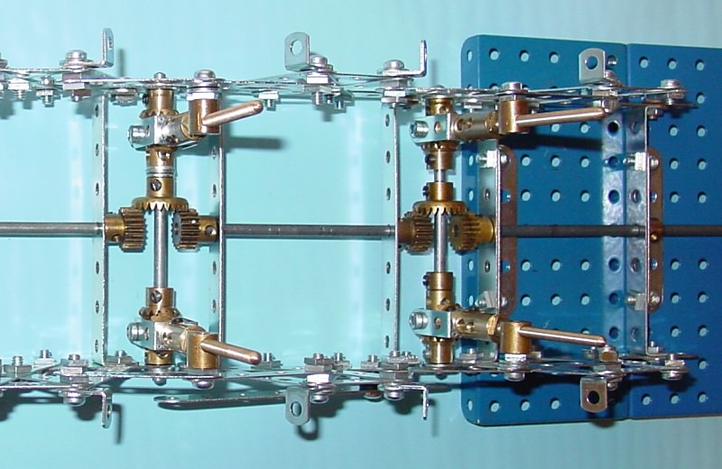
Figure 7 Contrate and pinion transfer gearing
A solution to this was to drive two opposing 25-tooth contrate gears from the 19-tooth input pinion of each stage and couple the contrate gears to the screw jack bevel gears with short Socket Couplings (part 171a), free running on the hinge axle rod. This reverses the drive to each jack so that with right hand threaded parts, both jacks extended together, and eliminates the friction associated with rotating the hinge axle rod.
Now the transfer drive pinion prevented articulation of the sections. So I thought of using a 15-tooth carry-over Pinion (part 26c), but that altered the ratio between each section and produced the wrong direction of rotation again!
The next solution was to arrange a reversing drive between each section, which also corrected the ratio difference. I had not photographed all the developments up to this stage, except for figure 8, which shows the 19-tooth reversing gears on the left with 25-tooth narrow face Pinion (part 25v) and 15-tooth Pinion (part 26c) ratio correction gears to the right.
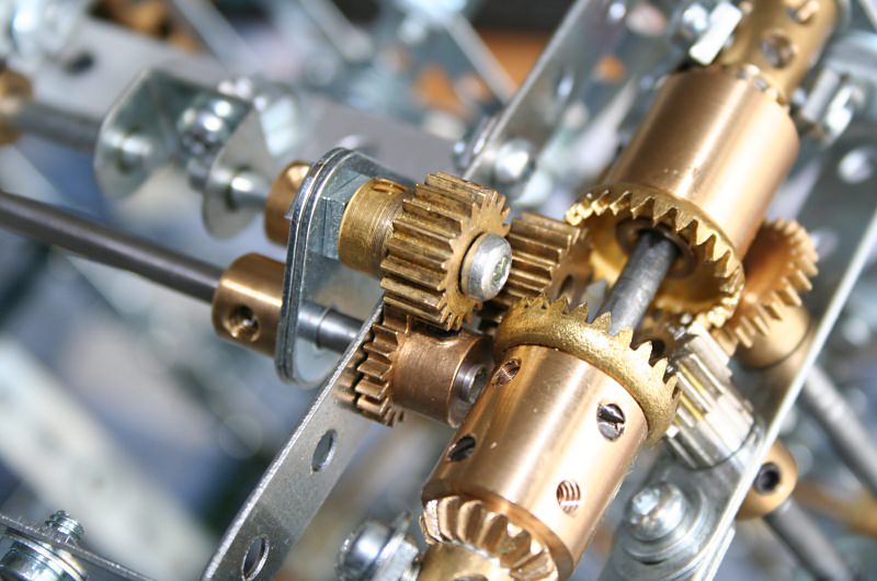
Figure 8 Reversing and ratio correction gearing to screw jacks
Constructing three of these drives between four bridge sections proved the principle, but the friction generated by the extra gearing cancelled-out that saved by not driving the hinge axles. Also, the strain on the first stage pinion/contrate mesh demonstrated the limitations of contrate gears by the amount of wear and indentation taking place, after only a few cycles of operation.
The next idea was to use bevel gears instead of contrates, but this was fraught with difficulties in correcting the ratio between drive and carry-over bevel pinions.
A period of reflection, deliberation and review followed during which I decided that an all-gear solution was unlikely to be sufficiently robust or efficient for the amount of power required to operate all five stages.
Electro-Mechanical Solution
I then considered driving each section with separate motors, provided a powerful enough motor could be found to drive the first stage of a complete bridge.
This may have the disadvantage of not articulating each bridge section at the same rate, because of the load differences across each section.
Also, I needed a very small diameter motor — ideally less than 20mm — to fit below the floor level. Whilst researching the availability of suitable motors, Jim McCulloch of the Holy Trinity Meccano Club introduced me to the geared motors available from Meccparts, New Zealand.
These are powerful 6–12V DC geared motors of various reduction ratios, with the particular advantage for this application of having the output shaft off-centre. This would enable me to offset the body of the motor below the bridge floor.
A sample 222:1 geared motor was purchased for experimental testing. Before investing in all the extra socket couplings and bevel gears needed for the complete system, I mocked-up a six stage bridge framework, driving the first stage with this geared motor and adding weight to the non-powered sections to simulate the whole mass. Encouragingly the motor handled the initial lift with ease. This is important because in operation, the centre of gravity of the complete bridge moves towards the mounting dock as each section articulates, thereby reducing the load on the primary motor.
The motors are mounted to 3½” x ½” Double Angle Strips (part 48b) which are drilled Ø2mm and countersunk for the screws supplied with the motors. Five Ø2mm washers on each screw provide clearance for the drive shaft boss. The motors are fitted with 12 tooth 45° Bevel Pinions (part 30g) driving 24-tooth 45° Bevel Gears (part 30b) to each screw jack. The 12/24-tooth bevels work quite well together despite the fact that they are not supposed to (their pitch cones are not conjugate) but their mesh conditions are certainly better than those of spur pinions and contrate gears.
The motor mounting and the bevel gearing to the screw jacks is shown close-up in figure 9.
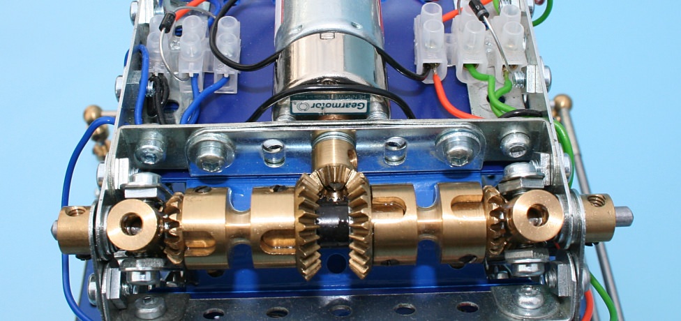
Figure 9 Motor mounting and drive arrangement
Now all I had to do was to build a complete bridge, with motor powered sections, to determine if each motor maintained sufficient speed to simulate the rolling action!
The resultant drive arrangement proved reasonably consistent in the rate of articulation of each section, but now some form of automatic switching was required to stop the motors independently at the end of each fold/un-fold motion. For this I added upper and lower normally closed limit micro-switches to terminate the run of the first stage motor, and tested it with just the first two sections assembled.
Then it was necessary to design a circuit that fed power to each motor and incorporate limit switches for each stage. This took some time but was resolved by arranging a double pole, double throw switch, to reverse the current to the motors and by wiring one set of limit switches to the positive rail, and the other set of switches to the negative rail. This appeared to work — on paper at least. Testing this arrangement proved otherwise because power feedback through the normally closed switches negated the open switches!
Now I had to learn about diodes — these would prevent the undesirable current feedback. Having selected and purchased suitable diodes, the circuit was revamped and the diodes wired-in, with a successful outcome. The final electrical circuit is shown in figure 10 and the physical layout of the bridge drives in figure 11.
Figure 10 Electrical circuit for six-element rolling bridge
After making small adjustments to the switching functions to ensure the bridge was level when extended and wrapped to the correct angles when rolled, the whole system operated successfully.
Unlike the actual bridge, the model is held level when extended (unrolled) by the screw jacks, resulting in the handrails being slightly raised to take-up clearances in the structural linkage. The joints and hinge points of the actual bridge are manufactured to precision engineering tolerances and clearances and the handrails are pulled slightly below the horizontal. This guarantees that a small component of load is directed downward, thereby ‘locking’ the geometry and ensuring the stability of the bridge under load and thereby forming a simple truss structure.
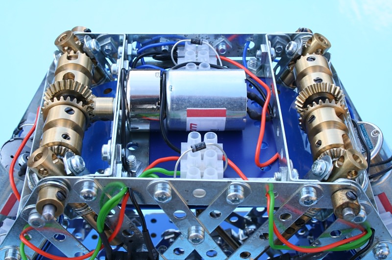
Figure 11 The folding drives
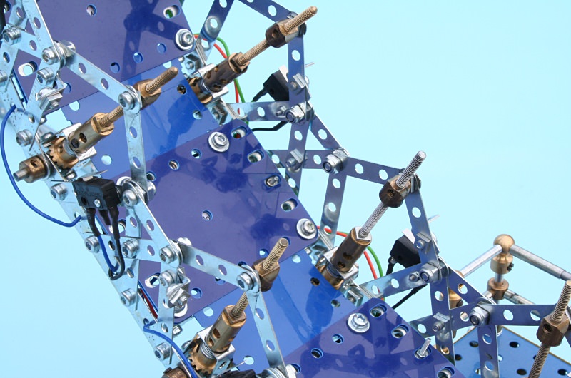
Figure 12 Screw jacks and structure
Decking and Docks
The walkway surface is made up of plastic plates to save weight. Each section has a pair of 3½” x 2½” Plastic Plates (part 194b) separated by a washer. Across each hinge point is a 2½” x 2½” Plastic Plate (part 194a), sandwiched between the 3½” x 2½” plates, fixed on one side and sliding between them the other side.
A mock-up base was originally used to test the model during its development. It was then necessary to design and build some form of dock arrangement to simulate the actual conditions. The model is mounted on a simple 2½” high dock, set back so as not to interfere with passing boats and fitted with safety handrails. The receiving dock is similarly constructed as shown in figures 13–15.
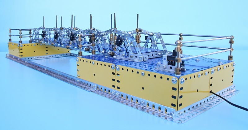
Figure 13 Bridge configuration (unfolded)
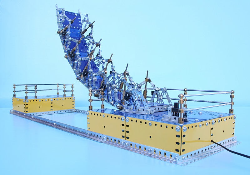
Figure 14 Rolling/curling
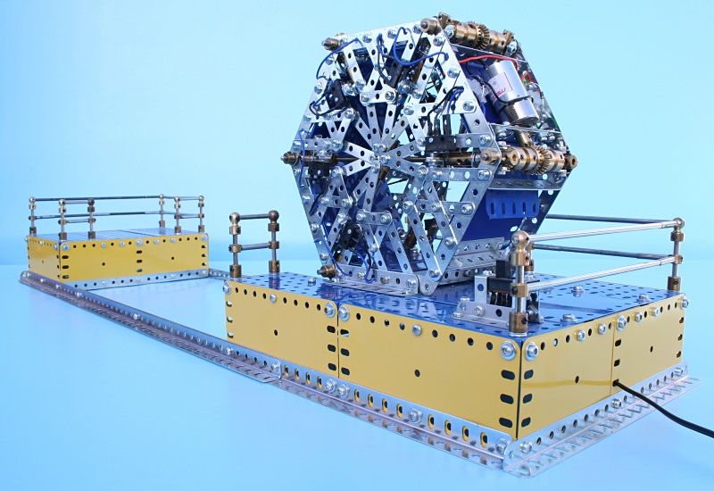
Figure 15 Closed (folded)
See more photos of this model.
Non-Meccano Parts List
| Part |
Quantity |
| Geared Motor |
5 |
| DPDT slide switch |
1 |
| Miniature micro switch/lever |
10 |
| Terminal block |
2 |
| 16/0.2 wire – black |
1 |
| 16/0.2 wire – blue |
1 |
| 16/0.2 wire – green |
1 |
| 16/0.2 wire – orange |
1 |
| 16/0.2 wire – red |
1 |
| Heatshrink sleeving |
1 |
| 1N4001 rectifier diode |
10 |
| 2mm washer |
50 |
This article © 2007 Alan Wenbourne.