Plasser & Theurer 08–475 Unimat Ballast Tamper
Written by Bryn Jones for our September 2011 Newsletter
Download this article in PDF format.
Introduction
This model was based on the design of three prototype machines owned by Queensland Rail in Australia. Because it was not possible to visit the machines to photograph them, we used some general arrangement drawings kindly supplied by Plasser Australia, and photographs supplied by Plasser & Theurer’s head office in Wien, Austria. Bryan’s knowledge of the design concepts of similar Plasser machines, which are owned by KiwiRail in New Zealand, was put to work in ‘guesstimating’ some of the unseen details.
The model ended up being the result of four years of research, design, construction and re-construction, with Laurie Webb producing the bodywork and bogies, and Bryan Jones producing the various mechanical sections.
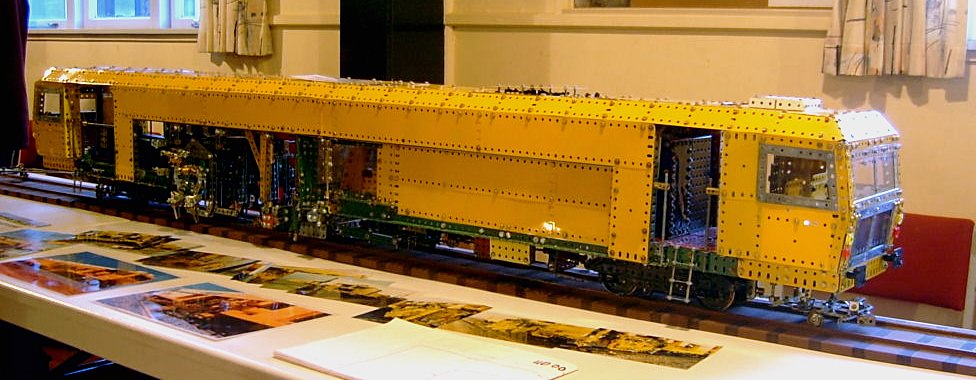
Figure 1 The completed model
What is a Ballast Tamper?
A ballast tamper is a machine which is used to correct and stabilise the geometry of railway track. It measures three parameters:
- The horizontal line (how straight the ‘straight’ tracks are, or the smoothness of curves)
- The vertical line (checking for dips in the track due to sunken rail joints or settling of the ballast formation)
- The cant (how much one rail is higher than the other, so that trains lean when they go around curves)
As it measures, the tamper has electronics which compare the measurements with the design parameter data for the track it is working on. If there are errors, the tamper uses hydraulic power to lift the track slightly and move it as required to correct the errors. It does this one sleeper at a time. While the track is held in its corrected position, tamping heads descend, and vibrating tines thrust into the ballast (the stones under and around the sleepers). The tines squeeze towards each other in a pincer-like movement to compact the ballast around and under the sleeper, which holds the track in its new position.
The machine is operated by one person, who sits in a central cab where he can see the sleeper being worked upon. He drives the tamper to the next sleeper and initiates the measurement/correction/tamping cycle. The machine does this automatically in approximately 3 seconds. If the tamper is tamping every sleeper along a length of track, it works at a rate of about 15 sleepers per minute, or about ¾km/hr.
The Model
Our model was built to a scale of 1:12, running on 3½” gauge track. As the prototype machine relies very much on hydraulics for movement of its various parts, we had to simulate the hydraulic rams, and only had the drive plus the tamping head movement mechanised. All other movements were modelled as much as possible, but had to be moved manually to place the model in different poses.
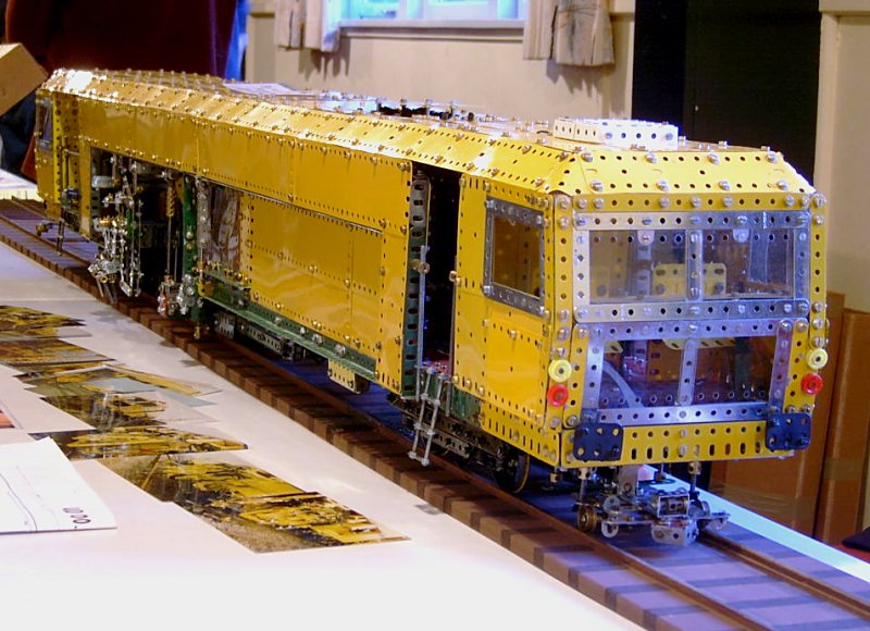
Figure 2 A front view of the model
Figure 2 shows the model from the front end. A driving cab sits over the front measuring buggy. Behind the steps is the enclosed engine compartment, and then the central work cab. Beyond this is the lifting frame and the tamping heads. At the rear is a driving cab for travelling in reverse and the rear measuring buggy is being towed behind the tamper.
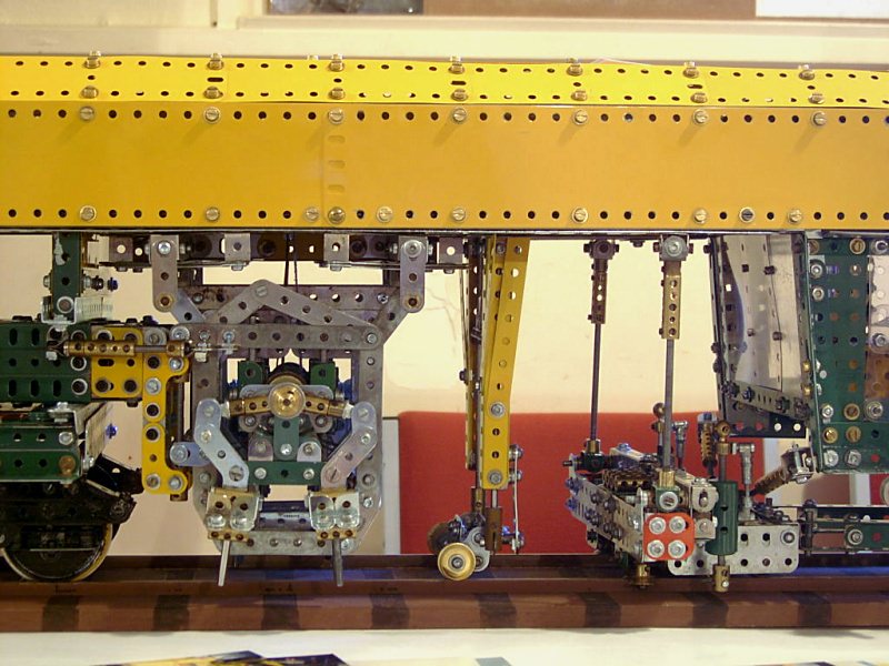
Figure 3 The work area
Figure 3 shows the work area of the tamper from the right hand side. The operator sits in the work cabin at right, and faces the back of the machine.
Immediately under and to the rear of the cab is the clamp frame. This has gripping rollers, simulated by ½” pulleys, which on the prototype machine grip under the head of each rail. The model has simulated hydraulic rams to lift the frame, thus lifting the track, and inclined rams under the work cab to push the track sideways. Because of the long wheelbase of the prototype tamper, there is enough room between the bogies for the rails to flex when force is applied.
In the centre of the photo is another measuring buggy. On the prototype there is a steel wire stretched between the front and rear measuring buggies, at just above rail height under the central axis of the tamper. This central buggy measures the error between the wire and the central axis, which provides the measurement of horizontal straightness. Two similar wires inside the tamper roof, vertically above each rail, provide the measurements for vertical straightness. A pendulum mounted on this buggy measures the cant.
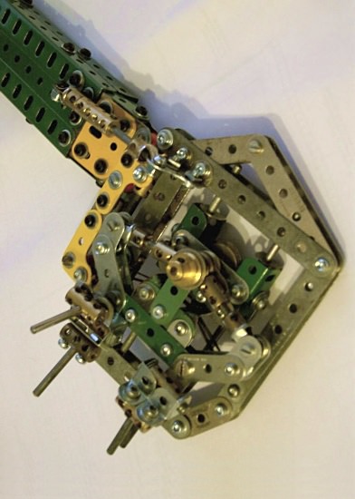
Figure 4 Outer right tamping head and support arm
To the rear of the measuring buggy, and just ahead of the rear bogie, is the tamping head assembly. On this machine there are four independent heads, which generally work together. Figure 4 shows details of the outer right hand head and support arm.
Each head consists of a carrier (the green parts in the centre) and two sets of tines, represented by 1½” rods mounted in Couplings. The tines are at the bottom end of Z-shaped levers, which are attached to the carrier via Pivot Bolts. At the top end of the levers are short hydraulic rams (short Couplings) which attach them to two eccentrics (represented by ½” Pulleys) on a shaft which rotates rapidly. This provides vibration which is transmitted to the tips of the tines, and the rams provide the squeeze movement. The shaft is represented by a 1¾” rod, with a ½” Pulley with Boss at the outboard end to represent the hydraulic drive motor. A 1” Pulley on the inboard end represents a flywheel.
Because of the scale we used, it was not possible to make working vibration components, and the squeeze movement was held in the ‘un-squeezed’ position by rubber band, so that the squeeze movement could be demonstrated manually. In the photo the rubber band can be seen, and the tines are held in the squeezed position by a couple of Grub Screws in the Short Couplings for the photo.
Each tamping head is carried on vertical slides in a frame. The four frames are normally arranged in pairs inside and outside of each rail. In the prototype a hydraulic ram lowers the carrier quickly so that the vibrating tines are thrust into the ballast on either side of a sleeper, and then withdrawn again after the squeeze cycle. The tines are lifted clear of the sleeper so that the tamper can proceed to the next sleeper. In our model a string from each carrier was run back via pulleys to the engine compartment, where an intermittent motion mechanism was used to lower and raise the heads.
As mentioned, the four head frames normally sit in pairs above each rail. The Unimat Tamper is also able to tamp turnouts and crossings, where other rails sit at an angle to the rails upon which the tamper is sitting. The heads must be able to move independently so that the tines can work in the irregular spaces formed by the sleepers and rails in these situations.
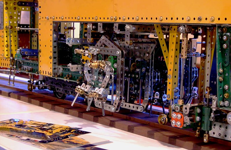
Figure 5 The outer frame movement
Figure 5 shows how the outside frame can swing away from the inner frame. It is carried on a sliding arm, which pivots at its rear end, and which has a wrist joint so that the frame may be pivoted at an angle. It may be seen that the inner frames are hung from two axles, representing horizontal columns. In the prototype, hydraulic rams can move these inner frames sideways on the columns. Also, the tines on each carrier are in pairs, an inner set and an outer set. As shown in Figures 4 and 5, the outer set can be swung up to allow the inner set to fit into tight spaces in turnouts. For ordinary track the outer set swings down to be parallel to the inner set.
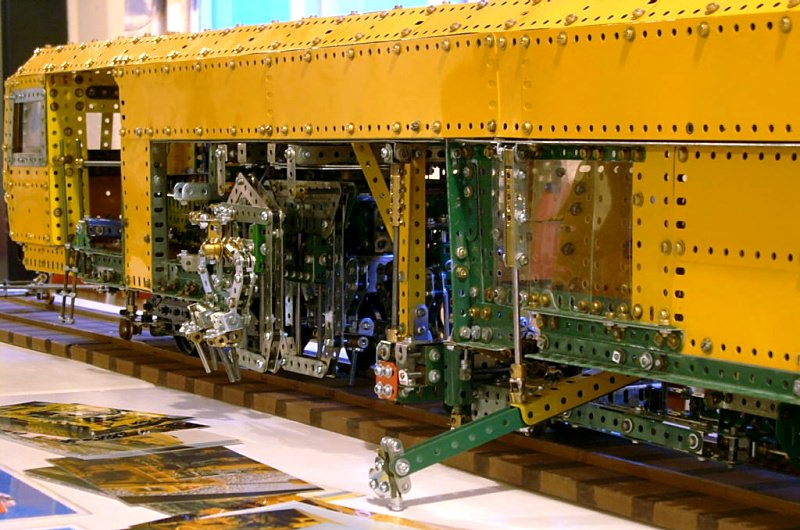
Figure 6 The tines in their normal position and the lifting arm
Figure 6 shows the tines in their normal position. It also shows the lifting arm which is deployed while tamping turnouts. The diverging rails of a turnout provide an out-of-balance load for the clamp frame to lift, so this telescopic arm locks onto the outer rail and lifts at the same time as the clamp frame. This keeps the turnout geometry flat. There is a similar arm on the opposite side of the machine.
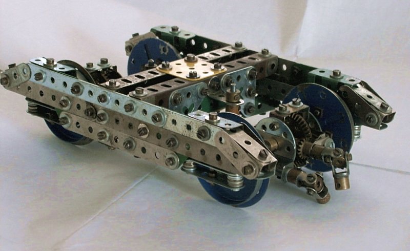
Figure 7 One of the bogies
The tamper rides on two bogies, the front one of which is powered. Apart from the driving mechanism, the bogies are identical, and an early mock-up can be seen in Figure 7. The coil springs carrying the axle boxes are represented by stacks of alternate thick and thin washers. The use of Wheel Flanges and Face Plates for wheels worked out very well for our chosen scale.
Each axle is driven via a propeller shaft and right angle gearbox. Plasser & Theurer builds these as individual units, offset towards one end of the axle, and the propeller shaft is in line with the axle, not as a hypoid arrangement as would be found in a tandem axle truck. The other axle is turned around and its propeller shaft is extended via universal joints so that both shafts appear at one end of the bogie. Because the shafts must be contra rotating for both axles to turn the same way, a splitter box is mounted after the machine’s gearbox, and two propeller shafts connect this to the bogie.
Our model used two small Meccaparts motors to drive the bogie, and despite the weight, these moved the model at a speed typical of what the prototype would use for moving from sleeper to sleeper. A Power Drive Unit was used to run the intermittent mechanism for operating the tamping heads. The motors were controlled by relays operated by a remote control on a long lead, pushbuttons allowing Forward and Reverse Travel, and Head Cycle.
The track used for exhibition was 4.8m long, and consisted of thin wooden strips representing the rails rebated into lengths of custom wood, with sleepers drawn on. Power was supplied via two copper strips laid between the rails, with pickups on the bogies.
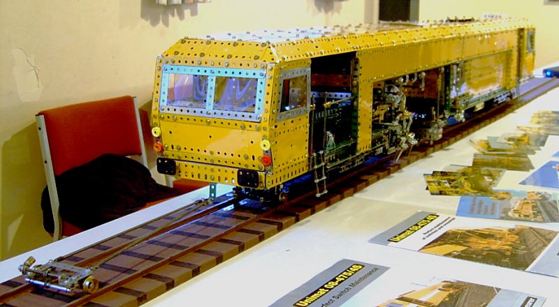
Figure 8 A rear view of the model
Figure 8
A view of the rear end of the tamper is seen in Figure 8. The rear measuring buggy, towed behind the tamper, is on the prototype the rear anchor point for the chord for measuring the horizontal alignment. The longer the chord, the more accurate the measurement, and it is usual to arrange the chord so that the measurement point is about halfway along the chord. This necessitates the rearward extension of the chord to a point beyond the mainframe, so a trailing buggy is often used.
Most of the photos in this article were taken at a club meeting in Wanganui, New Zealand, where we had the brochures, plans and photos supplied by Plasser & Theurer displayed, as well as a laptop computer which ran a short promotional video of a real machine operating.
This article © 2011 Bryan Jones and Laurie Webb.