Digital Command Control for Meccano
Written by Les Chatfield for our Spring 2021 Newsletter
We have all had the problem of operating multiple motors with their attendant mare’s nests of wiring. Digital Command Control (DCC) offers a way around this. Instead of controlling each motor by varying its voltage, DCC controls motors by sending ‘commands’ along just two wires to all the motors on the model.
However, each motor is equipped with a decoder. The decoder picks up all the commands flowing through the two wires (railway track) but only acts on those that have its ‘address’ on them. So, going back to railways for a moment, I can have 50 locomotives on my layout, but only one will move when I operate the DCC controller.
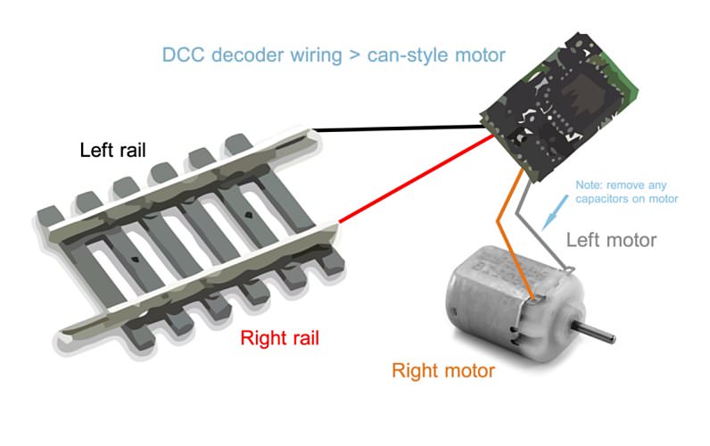
DCC was designed for model railways, hence the railway track in this diagram
Now forget about railway tracks. From now on we are using the two DCC devices (controller and decoder) in a model. Take the famous Block Setting Crane from the 1930s. This would normally need at least six wires passing from the controls to the rotating superstructure. We can cut this down to two! And if we use the metal of the model as a return, that is reduced to one!
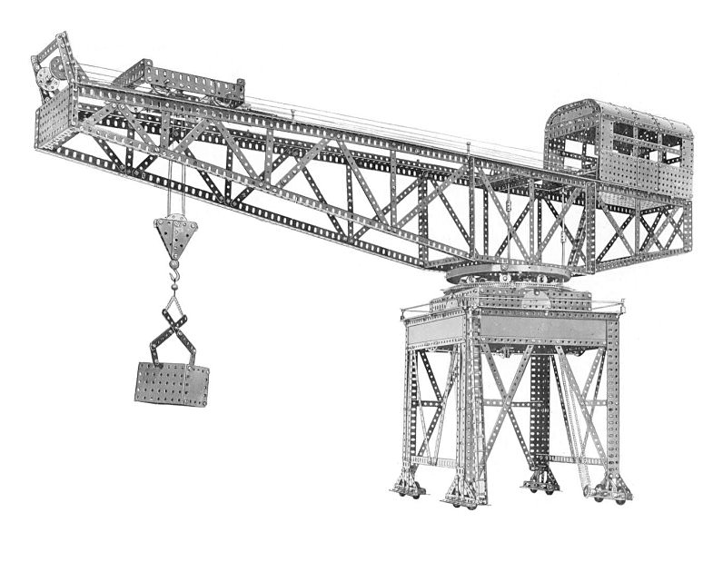
This fine Block Setting Crane would normally require at least three motors with six wires needing to pass into the rotating superstructure without binding. With DCC multiple motors can be controlled via just one wire!
This one wire comes up to the rotating superstructure via a slip ring (the Meccano Commutator will do just fine). This single wire connects to the three motors in the cab of the model (hoisting, crabbing and rotating). However, each motor is connected via its own decoder. Its black wire goes to the frame of the model and the red wire goes to the single wire from the slip ring. The remaining wires go to the motor. So now we have six decoders wired to their motors. Before we fit them to the model they must be set up. This is done by connecting each motor decoder assembly to the ‘programming track’ output of the controller. This process assigns the decoder’s ‘identity’ number (new decoders are always numbered 3). Other factors like top speed, acceleration and braking can also be set but these are more relevant to train control. On our model they can simply be numbered 1, 2 and 3. The decoders will not forget these settings even when disconnected from power.
In use the model is connected to the DCC controller via its single wire and a second wire from the structure of the model to the controller. Now let’s go! To make the crane hoist you select Loco 1. Then turn the traditional rotary controller. The motor on the model will receive its commands and start running at a speed and direction sent by the controller. Interestingly, if you now enter Loco 2 (motor 2), it too will start running but motor 1 will continue to run until you instruct it to stop! Because of the multiple controllability, all DCC controllers have a ‘Stop Everything’ button.
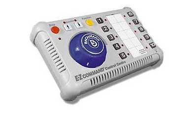
This DCC controller provides direct control of 10 motors
The decoders can usually drive motors drawing up to 1A, and because the controller is sending commands to the motors and not voltage variations, the model is continuously live (at 18V AC!) The actual motor voltage is varied by its decoder obeying commands from the DCC controller. So one could have lights etc. continuously lit by wiring them to the single power wire.